
Introduction
Today’s Arduino tutorial teaches us how to join DC Motor with Encoder using Arduino Uno. In this Arduino project, we will alter the voltage or current from the power supply, and accordingly, the encoder will change the DC motor’s speed.
The components can be purchased online, or websites like Tinkercad can be used to make this project.
Supplies
In order to join DC Motor with Encoder using Arduino Uno, we will require the following components:
Components
- Arduino Uno R3
- 1 DC Motor with Encoder
- H -Bridge Motor Driver
- 1 small BreadBoard
- 1 Resistor
- 1 LED
- Power Supply
- Connecting wires
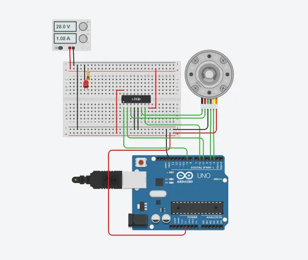
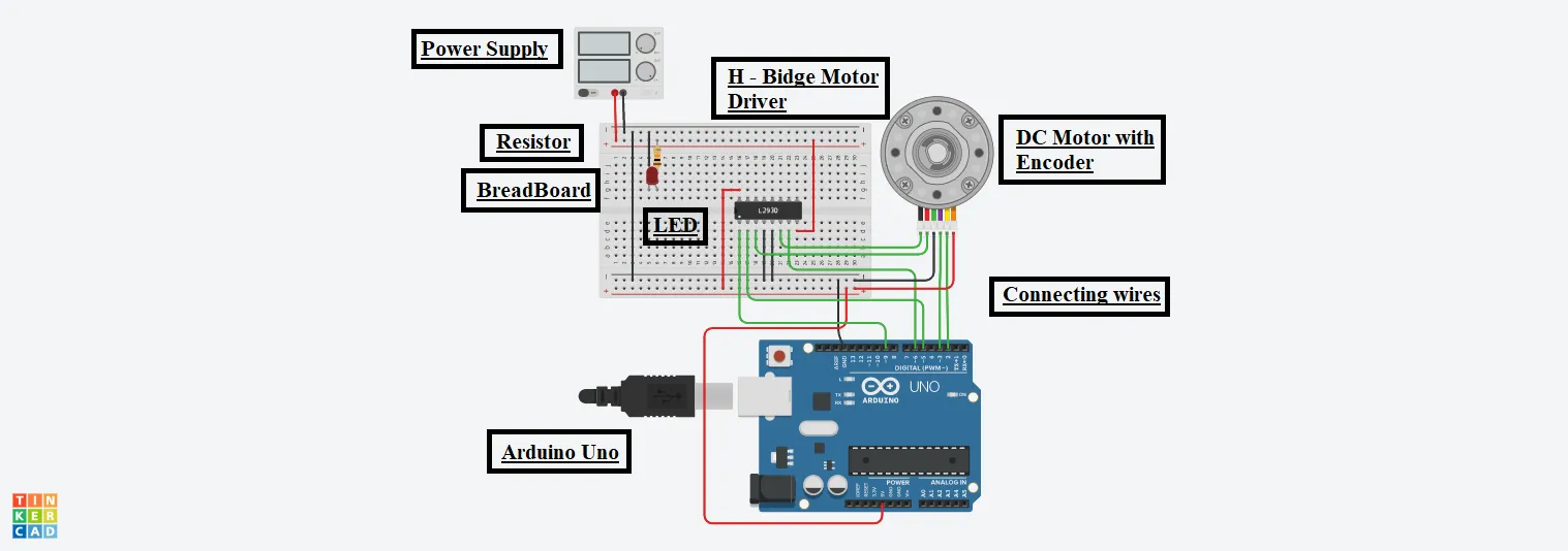
Circuit Diagram
Steps To Connect DC Motor With Encoder Using Arduino Uno
Step 1: Gather all the components in one place.
Step 2: Plug the H – Bridge Motor Driver on the BreadBoard.
DC Motor with Encoder:
Step 3: Connect the Motor Negative Terminal of it to the Output 2 pin of the H-Bridge.
Step 4: Connect the Motor Positive Terminal of it to the Output 1 pin of the H-Bridge.
Step 5: Connect the Encoder Ground terminal of it to the GND pin of the Arduino.
Step 6: Connect the Channel B terminal of it to the 3 number pin of the Arduino.
Step 7: Connect the Channel A terminal of it to the 2 number pin of the Arduino.
Step 8: Connect the Encoder Power terminal of it to the 5V pin of the Arduino.
LED:
Step 9: Connect the Cathode terminal of it to the GND pin of the Arduino.
Step 10: Connect the Anode terminal to the positive of the Power supply through a resistor.
H – Bridge Motor Driver:
Step 11: Connect the Power1 terminal of it to the 5V pin of the Arduino.
Step 12: Connect the Power2 terminal of it to the Positive Terminal of the Power Supply.
Step 13: Connect both the Ground terminals of it to the GND pin of the Arduino.
Step 14: Connect both the Input Terminals of it to the 5 & 6 number pin of the Arduino, respectively.
Step 15: Connect the Enable 1 & 2 Terminals of it to the 9 number pin of the Arduino.
Power Supply:
Step 16: Connect the Negative terminal of it to the GND pin of the Arduino.
Source Code
int input1 = 5;

int input2 = 6;

int enablePin = 9;

int LED = 13;

int encoderPinA = 2;

int encoderPinB = 3;

int encoderPos = 0;

float ratio = 360./188.611/48.;

float Kp = 30;

float targetDeg = 360;

void setup()

{

pinMode(encoderPinA, INPUT);

attachInterrupt(0, encoderA, CHANGE);


pinMode(encoderPinB, INPUT);

attachInterrupt(1, encoderB, CHANGE);


pinMode(LED, OUTPUT);

pinMode(input1, OUTPUT);

pinMode(enablePin, OUTPUT);

}

void loop()

{

float motorDeg = float(encoderPos) * ratio;

float error = targetDeg - motorDeg;

float control = Kp * error;


digitalWrite(enablePin, 255);

motor((control>=0)? HIGH : LOW, min(abs(control), 255));

}

void encoderA()

{

encoderPos += (digitalRead(encoderPinA) == digitalRead(encoderPinB))? 1 : -1;

}

void encoderB()

{

encoderPos += (digitalRead(encoderPinA) == digitalRead(encoderPinB))? -1 : 1;

}

void motor(bool dir, int val)

{

digitalWrite(input1, dir);

digitalWrite(LED, dir);

analogWrite(input2, dir?(255 - val):val);

}
Explanation of the Code
1. Firstly, we have initialized some variables of the components to the pin number of the Arduino to which they are connected.
2. After it, we have initialized the float ratio, in which 360 represents 1 turn, 188.611 is the gear ratio, and 48 is the motor shaft.
3. In the setup function, we have configured the pins for Input and Output purposes, respectively.
4. We calculate the motor degree, error, and control in the loop function. And then use functions to produce the desired output.
5. We have used conditional statements to get the values. If the statement is true, the first one will be considered. Else, the second one will be considered.
6. Finally, we are changing the encoder position w.r.t the encoder pin.
Output
On switching ON the Arduino, we will be able to control the speed of the DC motor by altering the Voltage or current from the Power supply, as shown in the figure.